Software Radio Baseband Digitizer PCB
I'm plugging away at building an inexpensive, high-bandwidth software-defined radio receiver. I built a bunch of PLL+VCO boards, filter boards, and quadrature mixer boards. But I still don't have a good ADC to sample the signals I'm receiving. No longer! I just submitted a four-layer design to Laen's Dorkbot PDX PCB Order, which should give me 10 MHz of bandwidth:
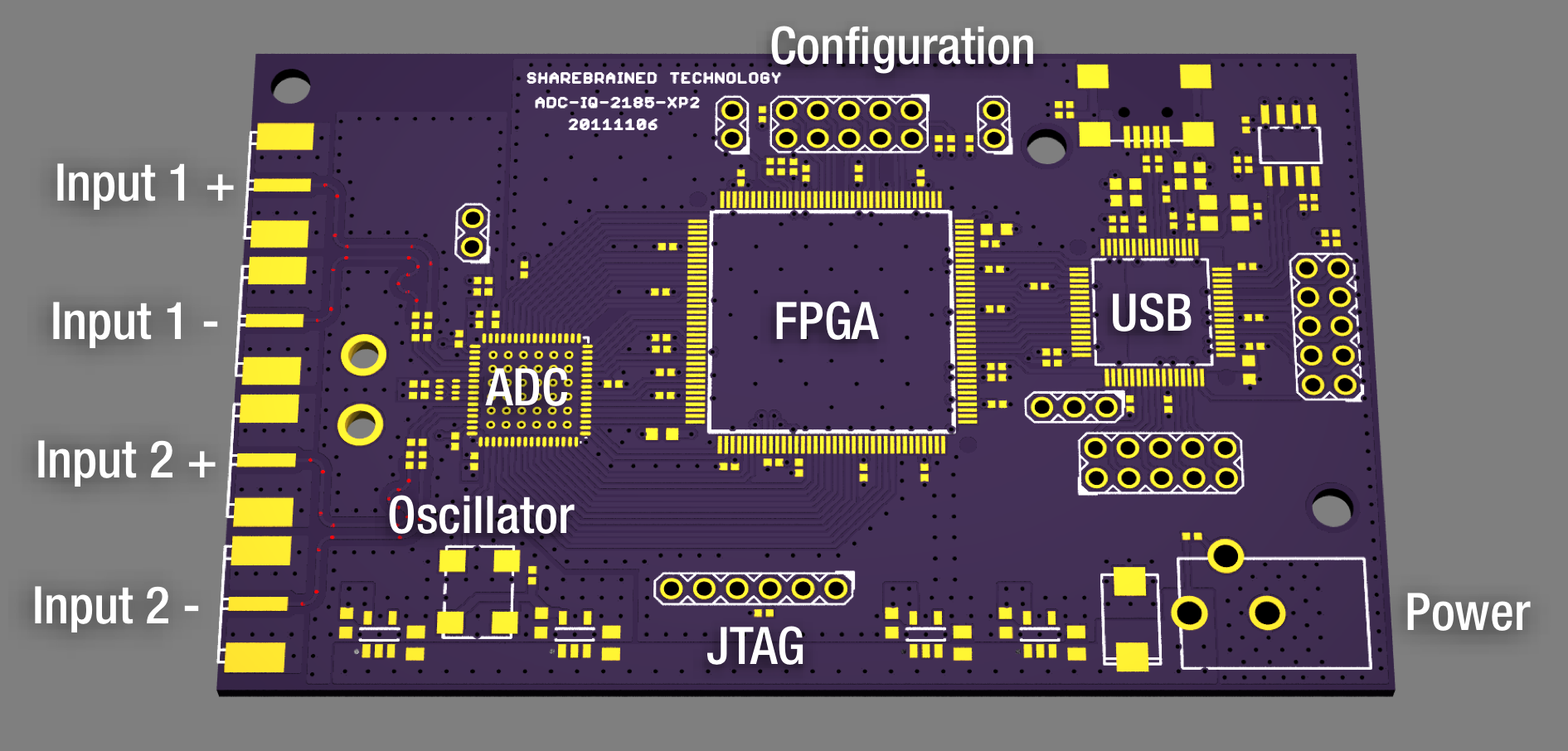
A quick overview of the board's design:
- SMA connectors for the baseband quadrature input signal. There are two differential inputs, so four connectors total.
- Two-channel high-speed ADC from Linear Technologies. I designed with the 16-bit, 125MHz LTC2185 in mind, but Linear offers many pin-compatible devices that are cheaper, with the attendant trade-offs in sample rate and resolution.
- Sampling oscillator in a standard 7mm x 5mm footprint. I'm planning to use a low phase noise oscillator like the Connor-Winfield CWX813.
- Lattice XP2-5 FPGA for sample rate conversion.
- FTDI FT2232H high-speed USB interface.
- Configuration and FT2232H pin breakout so I can experiment with USB-based FPGA code updating.
- JTAG interface for initial development.
- Power input – approximately 3.7V minimum.
USB 2.0 high-speed performance is a bottleneck for software radio. On a good day, you can get 35 MBytes/second. Assuming 12-bit quadrature signals, that gives you a complex sampling rate of about 12 MSamples/second, and a theoretical bandwidth of 12 MHz. Usable bandwidth will be more like 10 MHz.
Because of this USB-imposed bandwidth limitation, I chose to use a faster ADC to oversample the input and simplify the analog filtering going into the ADC. I'm expecting to oversample the baseband signal by 4x to 8x. With that amount of oversampling, simple four-pole Butterworth or Bessel filters should be plenty. The FPGA will do sample rate conversion, using CIC or FIR filters.
There's almost no filtering on the ADC input. I'm planning to attach a separate baseband filter or use an RF band-selection filter to severely band-limit my target signals and avoid unsightly aliasing. Here's one approach for an 80 MHz sampling rate and a 10 or 12 MHz output rate:
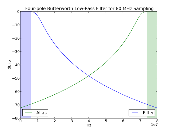
The great thing about oversampling is you don't have to design your analog filter for the final sample rate's Nyquist frequency. Instead, you can push that stop-frequency up to the sampling rate minus the final bandwidth. In the example above, it's 80 MHz minus 6 MHz, or 74 MHz. So my filter can gracefully tail off across more than a decade of frequency (74:6 = 12.3x). Of course, with oversampling, I've made a lot more work for myself in the digital domain. But FPGA CIC and FIR filter implementations are plentiful and well-understood, so I'm not too worried…
The board should be back from Laen in a couple of weeks. I can't wait to solder it up and see what happens!
Comments
It is wonderful development, I follow you Software Radio adventures with great interest. Did you consider something like software-based Bluetooth decoding, in the lines of Ubertooth? It can be technically possible with your bandwidth, as far as I understand.
Why Lattice FPGA? They have no free tools as far as I know, only time limited 6mo license.
Otherwise, impatiently wait for results.
Sorry for not following up about satellite - have nothing to add so far, need to learn (re-learn) some physics, but taking ml-class and ai-class instead ;-)
Decoding Bluetooth requires fast frequency hopping, which would be a function of whatever front-end tuning and downconversion you attach to this device. If you know the target's hopping sequence, you can certainly digitize a single Bluetooth channel with this device. You may also be able to capture the entire 2.4 GHz spectrum using this device and a 125 MSample/second two-channel converter. But you'd need to do a lot of work in the FPGA, since the USB interface would not support that much data to the computer. The FPGA would need to do some sort of channel energy monitoring, and selectively tune a NCO (numerically-controlled oscillator) to downconvert the active channel and resample it. You could then send those channel samples over USB, or proceed to demodulate it on the FPGA. A trick may be possible to simplify the FPGA's work – maybe resample the 2.4 GHz band so as to alias all the channels in the band into a single Bluetooth channel (or two channels complex?). In any case, it'd be fairly tricky to develop.
I went with Lattice because they had an interesting mix of features – low-cost, flash-based devices in LQFP packages, available from multiple distributors, with simple voltage supply requirements and multiply/accumulate blocks well-suited to high-speed FIR filters. But I'm not sold on them. One thing I'd like to have is built-in LVDS terminators, which I know the Xilinx Spartan-3As offer. And I'm waffling about wanting a flash-based device. When I was thinking I'd make a completely stand-alone device (no computer), it made more sense. But with the second interface on the FT2232H USB device, I can do FPGA initialization from the host.
Lattice recently introduced their [http://www.latticesemi.com/products/designsoftware/diamond/" target="new" rel="nofollow">Diamond] software, which is as free as the Xilinx and Altera tools. It's free as in beer, supports a limited number of their FPGA families, and runs on Windows and Linux. I think you must be thinking of their older software, which looks to be more limited.
Awwww… I'm on a Mac!
@Jeffrey: So am I! VMWare, Parallels, VirtualBox, Boot Camp? I'm still rocking my Windows XP install from 2003…
That dual ADC lists at about $145 at the Lattice website. It must be nice to have money.
I'd love to see your design [and software! ] but I'd have to change to a simpler, CHEAPER adc… LTC2258-12 (65Msps) is a single channel 40-pin QFN that lists at about $20. Clock it at 48MHz, simplifies your USB clock source. Generate a 60MHz IF signal and it undersamples as a 12MHz signal.
That simplifies your downconverter, your I / Q signal matching, leaves plenty of FPGA cells to either downsample more, -OR- FFT to find your signal, -OR- even try a wide bandwidth signal. Forget wide-band FM, I'm talking analog TV- [5 - 6 MHz wide].
@Alan: Linear is very good about providing samples, so you don't have to drop $145 on a converter for a prototype or two. Also, the ADC2185 is at the top end of what I'd use to populate this board. Linear produces a wide range of dual-input ADCs that run from 25Msps to 125Msps, and 12 bits to 16 bits. So my design can scale based on the amount of bandwidth and resolution you need. I'm using a 12-bit, 80Msps device for my prototype.
I prefer the two-channel, quadrature approach, as it greatly simplifies analog filtering requirements, and makes it easier to design a very wideband device with good adjacent-channel blocking characteristics. A single-channel, low-IF solution works well in a lot of applications, but usually requires a band-specific channel filter of some sort to be useful.
I'm getting close to having a proper channel filtering architecture working on my board – analog low-pass filters (cut-off of ~10MHz) combined with 10x decimation (from 80Msps to 8Msps complex). At that point, I should be able to pull down NTSC (if there are any left in my locale) or ATSC signals and demodulate them. I've already sampled a wide chunk of my local broadcast FM spectrum – without ANY analog or digital filtering – and it worked surprisingly well. It doesn't hurt that I'm receiving 50kW transmitters, I'm sure…
[…] confess, I've kept some secrets from you. The fancy software radio baseband digitizer I mentioned back in November? I got it working not long after, and I've had some fun with it (see demo video, below). Here […]
It is amzing development and too much intrested. I'd definitely be interested in playing with it.I'm working on getting Kismet to arbitrary capture from other Phy's (kickstarted by ubertooth), it should be plausible to get it.