Configuring the Citadel BBS for Kaypro
Citadel was one of the earliest bulletin board systems (BBS) systems, and started out on computers running CP/M. I happen to have several CP/M machines, mostly Osborne and Kaypro. I thought it’d be fun to get Citadel running on my Kaypro 2X, which has a built-in 300 baud modem. In retrospect, just about any other CP/M computer would’ve been easier, due to the very unsophisticated nature of the Kaypro 2X’s modem.
I started with the Citadel 2.10 binaries and source.
Configuration and Complications
At first, I tried the process outlined in the INSTALL.DOC file, without modifying the CTDLCNFG.SYS. CONFIGUR seemed to run OK, if slowly, on the Kaypro 2X. But when I ran CITADEL, it froze and I was unable to exit.
I decided to try a CP/M emulator, to shorten the iteration cycle, whih was slowed by the Kaypro’s 1980s-era performance and all the steps involved updating a GoTek floppy emulator disk image with a new configuration file.
The emulator was able to run CONFIGUR just fine, but would crash or hang when interpreting the INITPORT modem initialization opcodes:
C>citadel
intrp-no opcod0intrp-no opcod195intrp-no opcod195
CONFIGUR and CITADEL do some funny business around writing and reading a region of program memory to a file. My hypothesis was that maybe the binary I was using had those variables in a different location and they were overwriting some of the program and causing the freeze.
I downloaded the BDS C compiler 1.6, but was unable to recompile the programs due to changes in the C library API. (Citadel source code used fcreat, which was replaced with the more familiar and modern fopen.) I didn’t want to port the programs to a newer C API, so I downloaded BDS C compiler 1.4, assuming it would still expose the old C API. And with that, I managed to recompile the programs.
Unfortunately, my binaries bore no improvement. CITADEL still crashed in the exact same way. However, since I’m compiling my own binaries, I can add printfs and debug! I instrumented the interpret function in 210MODEM.C, as that was where the intrp-no opcod messages were coming from.
C>citadel
C1DC op=4
C1DE op=6
C1E0 op=4
C1E2 op=6
C1E4 op=4
C1E6 op=6
C1E8 op=6
C1EA op=4
C1EC op=6
C1EE op=4
C1F0 op=6
C1F2 op=4
C1F4 op=6
C1F6 op=6
C1F8 op=6
C1FA op=4
C1FC op=6
C1FE op=2
INP(D8)
FFFF op=0
intrp-no opcod00 op=195
intrp-no opcod1951 op=3
4 op=2
INP(C3)
0 op=195
intrp-no opcod1951 op=3
4 op=2
INP(C3)
The interpret code walks through a set of opcodes contained in CTDLTABL.SYS that are used to read and write IO ports to access the modem hardware. Strangely, in this dump of the INITPORT opcodes, the interpreter seems to wander off to 0xFFFF after executing the first INP opcode. I couldn’t imagine why the code would cause that to happen. So I hypothesized that the RunCPM emulator I was using simply didn’t implement IO ports?
I loaded up MBASIC in the emulator, read the documentation, and tried doing an OUT.
A>mbasic
BASIC-85 Rev. 5.29
[CP/M Version]
Copyright 1985-1986  $  by Microsoft
Created: 28-Jul-85
34872 Bytes free
Ok
OUT 32, 100
…which caused RunCPM to terminate. Well, OK! That’ll definitely prevent me from getting very far with Citadel on RunCPM. I suppose that makes sense, as RunCPM wasn’t really intended to emulate CP/M hardware.
Just for fun, how about we try an INP?
A>mbasic
BASIC-85 Rev. 5.29
[CP/M Version]
Copyright 1985-1986  $  by Microsoft
Created: 28-Jul-85
34872 Bytes free
Ok
?INP(32)
 0
Ok
RunCPM seems OK with that.
So why is CITADEL freezing? Time to instrument the code some more… I finally tracked down the freeze to the call to interpret(pInitPort) from within modemInit.
if (!rcpm) {
	interpret(pInitPort);
	interpret(pHangUp);
}
Looking at interpret, it seems we’re freezing while executing the OUTSTRING opcode.
case OUTSTRING:
    while(*instr.pc) {
		pause(5);	/* SmartModem can't handle 300 baud	*/
		outMod(*instr.pc++);	/* output string */
    }
    instr.pc++; 				/* skip null	 */
    break;
Nothing too concerning there. But what’s in outMod?
/************************************************************************/
/*	outMod stuffs a char out the modem port 			*/
/************************************************************************/
outMod(c)
char c;
{
	while(!interpret(pMOReady));
	outp(mData, c);
}
Well of course. That while loop is waiting for the modem to become ready by executing the MOREADY interpeter instructions. And MOREADY is configured in CTDLCNFG.SYS to look at port 0xDD.
/************************************************************************/
/*	MOREADY returns nonzero if modem is ready for output, else 0	*/
/************************************************************************/
#start MOREADY x		/* routine to sense modem output OK	*/
#code INP DD			/* read modem status port		*/
#code ANDI 20			/* mask off output-ok bit		*/
#code RET x			/* return 20 (TRUE) if ok, else zero	*/
In the RunCPM emulator, do you think DD will ever return non-zero from a peripheral port that isn’t emulated? Of course it won’t. We learned that earlier when trying INP() with MBASIC.
So the net learning here is: you have to actually configure Citadel to work with your hardware! This should come as no surprise, but I apparently expected errors or warnings from Citadel in the case it wasn’t configured right. But this software is really pushing the limits of a system with only 60K of RAM and no real hardware abstractions. So if something’s not configured right, it just doesn’t work, or does crazy random stuff. All these fancy, modern operating systems and computers with bazillions of bytes of RAM and disk have made me soft. :-)
OK, so how do we do this? Let’s review CTDLCNFG.SYS and see what hardware-related bits (interpreter blocks that use INP or OUTP opcodes) we will need to reimplement.
/*	CARRDETECT returns nonzero value on valid carrier, else zero	*/
...snip...
/*	HANGUP breaks the modem connection.				*/
...snip...
/*	INITPORT sets up the modem port and modem.  No return value.	*/
...snip...
/*	MIREADY returns nonzero value if modem char can be input, else 0*/
...snip...
/*	MOREADY returns nonzero if modem is ready for output, else 0	*/
Five “functions” shouldn’t be too hard.
Understanding the Modem Hardware
Let’s figure out the modem hardware. Here’s the portion of the Kaypro schematic that shows the built-in 300 baud modem.

The modem is implemented using the TMS99531 pulse and tone telephone dialer and TMS99532 FSK modem ICs.
The modem signals are connected as follows:
| Device | Signal | Description | Dir | Active | Connections |
|---|---|---|---|---|---|
| modem | ATE# | answer tone enable | I | L | PIO B4, dialer TT#/P |
| modem | ALB | analog loopback | I | H | PIO B5 |
| modem | RCVD | receive data | O | SIO-2 RXTB | |
| modem | XMTD | transmit data | I | SIO-2 TXDB | |
| modem | A#/O | answer#/originate | I | H=Orig | SIO-2 DTRB# |
| modem | SQT | squelch transmitter | I | H | SIO-2 RTSB# |
| modem | DCD# | data carrier detect | O | L | SIO-2 DCDB#, speaker enable |
| dialer | NB1 | digit select 0 (LSB) | I | PIO B0 | |
| dialer | NB2 | digit select 1 | I | PIO B1 | |
| dialer | NB3 | digit select 2 | I | PIO B2 | |
| dialer | NB4 | digit select 3 (MSB) | I | PIO B3 | |
| dialer | TT#/P | touch-tone#/pulse | I | L=Tone | PIO B4, modem ATE# |
| dialer | DP | digit present | I | H | PIO B7 |
| dialer | PND | present next digit | O | H=Ready | PIO BSTB# |
| relay | coil | off-hook INV/NAND | I | L=OnHook | PIO B6, dialer PULSE |
| ring? | ring detect? | O | SIO-2 CTSB# |
A few observations:
- The modem does nothing on its own. It relies on the Kaypro processor to do everything.
- We won’t need to deal with the dialer IC, I think, because Citadel only takes incoming calls and does not dial out.
- We can set A#/O=L, since we’re only ever answering.
- We can set ALB=L to disable loopback.
- ATE# should be high, since I’m preferring to implement Bell 103, and don’t want to produce a CCITT V.25 answer tone.
Hey, how do we answer a call? Citadel assumes the modem is intelligent and will be initialized to auto-answer, which is not the case on the Kaypro. We’ll have to detect that the phone is ringing, take the line off-hook, and wait for a carrier to be detected. These are things a fancier modem (usually implementing the Hayes command set) would do for us.
So how does the Kaypro modem detect a ring? I see an optoisolator circuit across the telephone wire-pair, going into an opamp and logic gate, and then into the CTSB# pin on serial I/O chip (SIO) #2. Watching that signal with a multimeter while an inbound call is ringing, we see it go high during the ring. With that in mind, here’s an MBASIC program that reads the SIO-2 CTSB#.
10 OUT &H0F, &H10
20 A = INP(&H0F)
30 IF A AND &H20 THEN GOTO 100
40 GOTO 10

100 PRINT "RING"
110 OUT &H0F, &H10
120 A = INP(&H0F)
130 IF A AND &H20 THEN GOTO 110
140 GOTO 10
How do we answer a call? The off-hook relay is activated by parallel I/O chip (PIO) pin B6 and the pulse output of the dialer IC. The signal has an inverting buffer between the PIO pin and the relay coil. So if we write a 0 to PIO port B data register (port 33), bit 6, we should close the relay and go off-hook?
PRINT INP(&H21)
 64
Ok
OUT &H21, &H00
Ok
…and sure enough, the line goes off-hook!
I spent some time probing around the AY-5-8116 baud rate generator, to see how it was configured by the Kaypro BAUDM and BAUDP programs. BAUDM configures the FR output (pin 3), which is connected to SIO-1’s RXCA and TXCA pins, which determine the baud rate on the serial data port (SIO-1 port A). BAUDP configures the FT output (pin 17), which is connected to SIO-2’s RXCA and TXCA pins, which determine the baud rate for the serial printer port (SIO-2 port A). The baud rate generator outputs 16x the selected baud rate (e.g. choosing 9600 baud produces 153.6 kHz). The baud rate for SIO-1 port B (keyboard) and SIO-2 port B (internal modem) are determind by a 4800 Hz clock from the 81-194 custom IC. The upshot is it looks like, for the 300 baud internal modem, I don’t need to do any baud rate configuration at all.
I should be able to make dialing tones when off-hook. The PIO port B data register is at IO port 0x21. We need to write port B, bits 0-3 for the DTMF value, and bit 7 to tell the tone generator that a new digit is present. Here’s an example of manually dialing
OUT &H21, &H80
Cool, it beeps! But I digress… Citadel doesn’t need to dial out. We’re only answering incoming calls.
The SIO has a feature where when a data carrier is detected (DCD), the serial receiver will be enabled. It can also enable the serial transmitter when clear-to-send (CTS) is true. Since CTS is off-hook and DCD is… carrier detect, that sounds good to me. However, we need to manually react to the ring indication and go off-hook anyway. So why not enable RX and TX manually, for simplicity’s sake. And is there any harm to just leaving RX and TX enabled all the time? We’ll try that.
When we answer the phone, we need to send the answer tone – 2100 Hz for V.21 and 2225 Hz for Bell 103. This is controlled by the TMS99532 ATE# signal. We also want to use the high band of frequencies, as the originating modem will use the low band.
Bell 103 Transmit and Receive Tones
| Symbol | Answer | Originate |
|---|---|---|
| Mark | 2225 Hz | 1270 Hz |
| Space | 2025 Hz | 1070 Hz |
I used the frequency counter on my multimeter, measuring across the telephone line transformer, to verify the answer tone was the correct frequency.
I iterated a bunch on an MBASIC prototype of the SIO2 and PIO configuration, call state management, and character input/output. I eventually settled on this program, which waits for the line to ring, goes off-hook, sends an answer tone, waits for a carrier, and then sends and receives data until the carrier is lost, at which point it hangs up and reinitializes everything.
10 REM SIO2 port B: reset "channel"
11 OUT &HF, &H18

15 REM SIO2 port B WR2: clear interrupt vector
16 OUT &HF, &H2
17 OUT &HF, &H0

20 REM SIO2 port B WR4: set 16x clock, 1 start, 1 stop, no parity
21 OUT &HF, &H14
22 OUT &HF, &H44

30 REM SIO2 port B WR3: set RX to 8 bits
31 OUT &HF, &H3
32 OUT &HF, &HC1

40 REM SIO2 port B WR5: set TX to 8 bits, enabled, no squelch
41 OUT &HF, &H5
42 OUT &HF, &HEA

45 REM SIO2 port B WR1: clear interrupt control
46 OUT &HF, &H11
47 OUT &HF, &H0

50 REM PIO: No V.21 answer tone, no loop-back, on-hook
51 OUT &H21, &H50

100 REM *** Detect Ring ***
101 OUT &HF, &H10
102 RR0% = INP(&HF)
103 IF RR0% AND &H20 THEN GOTO 200
104 GOTO 100

200 PRINT "RING"
201 REM Go off-hook.
202 OUT &H21, &H10

300 REM *** Carrier Detect ***
301 OUT &HF, &H10
302 RR0% = INP(&HF)
303 IF RR0% AND 8 THEN GOTO 400
304 GOTO 300

400 PRINT "CARRIER"
406 TX%=48
407 FOR I%=0 TO 1024
408 NEXT I%
410 OUT &HF, &H10
420 RR0% = INP(&HF)
430 IF RR0% AND &H1 THEN GOSUB 500
440 IF RR0% AND &H4 THEN GOSUB 600
450 IF RR0% AND &H8 THEN GOTO 410
460 GOTO 900

500 REM *** Receive Byte ***
510 RX% = INP(&HD)
520 PRINT CHR$(RX%);
530 RETURN

600 REM *** Transmit Byte ***
610 OUT &HD, TX%
620 TX% = TX% + 1
630 IF TX% > 57 THEN TX%=48
640 RETURN

900 REM *** No Carrier ***
910 PRINT "NO CARRIER"
920 GOTO 10
In the process of working on the MBASIC prototype, I was getting garbage on my originating terminal (my laptop running minicom). I was expecting a repeating “0123456789”.
atd1
CONNECT
�6��35�9�35�0��6�0��69�35�9�35�0��6�0���9�35�9�36�0��6�0�5�9�35�9��6�0��6�035�9�35�9��6�0��6�035�9�35�9��6�0��69�35�9�35�0��6�0���9�35�9�36�0��6�0�5�9�35�9�36�0��6�0�5�9�35�9��6�0��6�035�9�35�9��6�0��69�35�9�35�0��6�0��69�35�9�35�0��6�0���9�35�9�36�0��6�0�5�9�35�9��6�0��6�035�9�35�9��6�0��6��35�9�35�0��6�0��69�35
It turns out I was mistaken to use 7E1 as the serial characterstics for the modulator. 300 baud modems expect the modulated carrier to have eight bits, no parity, and one stop bit.
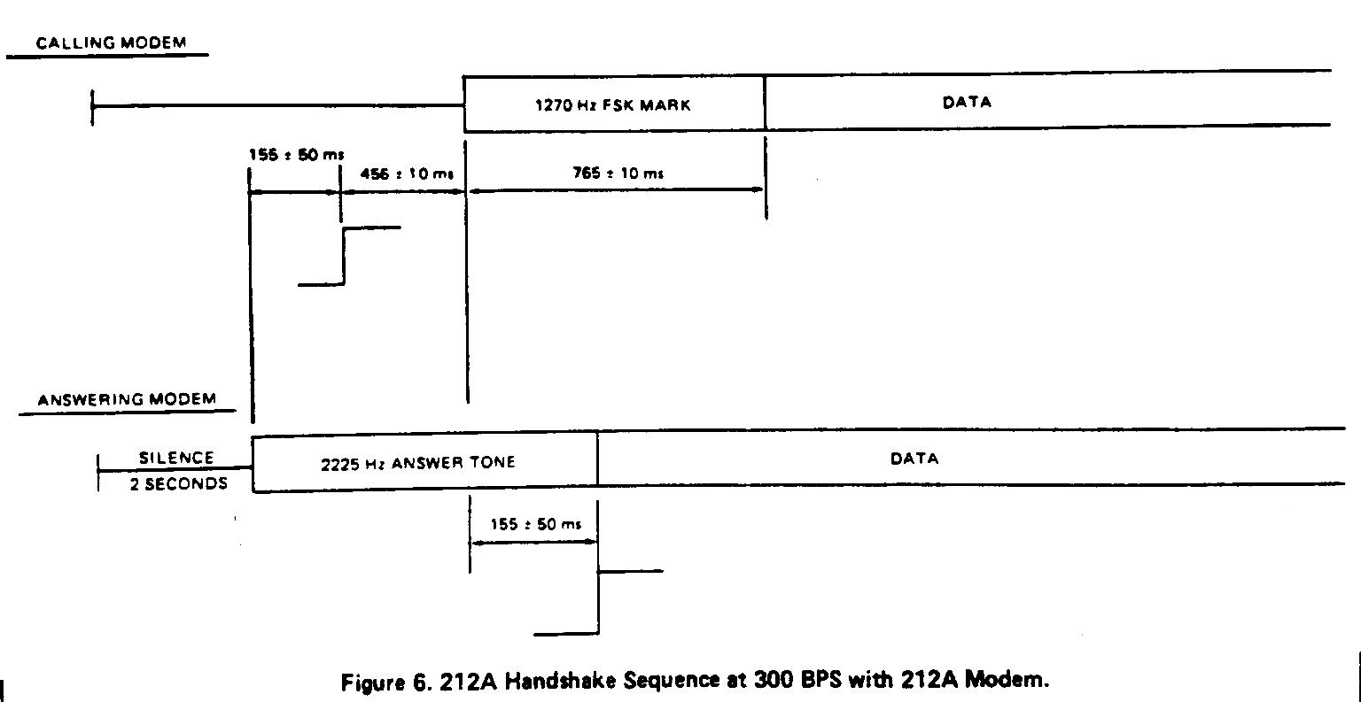
Even with that change, I was still getting garbage! But only on some calls. It turns out if you immediately start transmitting on connect, the other modem (even fancy USR V.Everything modems) don’t always synch up and you’ll receive garbage. So I added a pause after carrier detect and before transmitting. I later found an interesting diagram in a 2400-baud modem evaluation kit manual that indicates that a pause is required between answering the line and sending the answer tone.
So I think I have all the necessary pieces to operate the Kaypro modem.
Making Changes
I made a bunch of modifications to the Citadel CTDLCNFG.SYS to configure the Kaypro internal modem.
First up, we need to tell Citadel what IO port address to use to read and write data via the serial port.
/* MDATA is the port Citadel will attempt to read and write modem data	*/
/* from.  We expect 8-bit bytes, naturally...				*/
#define MDATA 0D		/* Modem data port			*/
I added a RINGDETECT interpret block, since the modem doesn’t auto-answer.
/************************************************************************/
/*	RINGDETECT returns nonzero value on ring, else zero	*/
/************************************************************************/
#start RINGDETECT x		/* routine to sense valid carrier	*/
#code LOADI 10			/*					*/
#code OUTP 0F			/* SIO2 port B: RR0 with status reset */
#code INP 0F			/* read modem status port */
#code ANDI 20			/* mask off CTS (ring) bit */
#code RET x			/* return 20 (TRUE) if carrier else 0	*/
I added code to the Citadel C source code to use this interpret block to check for a ring when no carrier was present, and take the line off-hook when a ring is detected.
CARRDETECT resets the sticky bits in order to read the current DCD# state, which indicates a carrier is detected.
/************************************************************************/
/*	CARRDETECT returns nonzero value on valid carrier, else zero	*/
/************************************************************************/
#start CARRDETECT x		/* routine to sense valid carrier	*/
#code LOADI 10			/*					*/
#code OUTP 0F			/* SIO2 port B: RR0 with status reset */
#code INP 0F			/* read modem status port */
#code ANDI 8			/* mask off DCD (carrier) bit */
#code RET x			/* return 08 (TRUE) if carrier else 0	*/
HANGUP simply opens the relay on the telephone line, putting the line on-hook.
/************************************************************************/
/*	HANGUP breaks the modem connection.				*/
/************************************************************************/
#start HANGUP x 		/* routine to break modem connection	*/
#code LOADI 50			/*					*/
#code OUTP 21			/* PIO port B: on-hook, no V.21 answer, no loop-back */
#code PAUSEI 50 		/* half a sec, then	*/
#code OUTP 0F			/* clear events */
#code RET x			/* No interesting value returned.	*/
INITPORT does configuration of SIO-2 and the PIO as described in the earlier MBASIC program.
/************************************************************************/
/*	INITPORT sets up the modem port and modem.  No return value.	*/
/************************************************************************/
#start INITPORT x		/* routine to initialize modem port	*/
#code LOADI 18			/*					*/
#code OUTP 0F			/* SIO2 port B: Reset channel */
#code LOADI 14			/*					*/
#code OUTP 0F			/* SIO2 port B: select WR4, reset ESI */
#code LOADI 44			/*					*/
#code OUTP 0F			/* SIO2 port B: WR4: clock, stop bits, parity */
#code LOADI 03			/*					*/
#code OUTP 0F			/* SIO2 port B: select WR3 */
#code LOADI C1			/*					*/
#code OUTP 0F			/* SIO2 port B: WR3: RX 8 bits, enabled */
#code LOADI 05			/*					*/
#code OUTP 0F			/* SIO2 port B: select WR5 */
#code LOADI EA			/*					*/
#code OUTP 0F			/* SIO2 port B: WR5: TX 8 bits, enabled, no squelch */
#code LOADI 50			/*					*/
#code OUTP 21			/* PIO port B: on-hook, no V.21 answer, no loop-back */
#code RET x				/* return nothing interesting		*/
MIREADY checks if there’s a received character waiting in SIO-2.
/************************************************************************/
/*	MIREADY returns nonzero value if modem char can be input, else 0*/
/************************************************************************/
#start MIREADY x		/* routine to sense modem char available */
#code LOADI 00			/*					*/
#code OUTP 0F			/* SIO2 port B: RR0 with status reset */
#code INP 0F			/* read modem status port */
#code ANDI 1			/* mask off char-ready bit */
#code RET x			/* return 1 if char ready, else zero	*/
MOREADY checks if the SIO-2 transmit buffer is empty.
/************************************************************************/
/*	MOREADY returns nonzero if modem is ready for output, else 0	*/
/************************************************************************/
#start MOREADY x		/* routine to sense modem output OK	*/
#code LOADI 00			/*					*/
#code OUTP 0F			/* SIO2 port B: select RR0 */
#code INP 0F			/* read modem status port */
#code ANDI 4			/* mask off char-ready bit */
#code RET x			/* return 4 (TRUE) if ok, else zero	*/
We need to change the clock frequency to 4 MHz, since the Kaypro 2X’s Z-80 processor runs at that speed.
/* MEGAHZ is the 8080-equivalent clock rate, used for busy-wait loops	*/
/* various places -- in particular, in the WC-protocol code.		*/
#define MEGAHZ 4		/* Z80 clock rate (for wait loops)	*/
While I was at it, I also changed the permitted range of years in the date scheme. We’re good now through Y2K37.
#code OPR# "Year" 20 37 /* get year from console */
It Works!
And with all that, we have a working Citadel BBS on a Kaypro 2X!

You can find all the configuration code changes, plus the source code changes in my project repository.
Assorted Notes
Exiting MBASIC and returning to the operating system:
SYSTEM
Saving an MBASIC program as ASCII, instead of the tokenized default:
SAVE "FILENAME.TXT",A
Retrieving a file from a CP/M image, on my Linux computer:
$ cpmcp -f kpiv 0:floppy.img modem13.txt .