PCB stencils on the cheap (kinda)
I'm in a heavy prototyping phase with my software-defined radio projects. Every time DorkbotPDX has a board order, I make sure I've got one or two boards in the order. Of course, once I get the boards, I have to assemble them. And since radio-frequency projects involve high frequencies, small surface-mount components are essential.
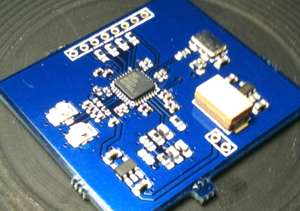
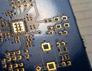
How small? It's common to use "0402" resistors, capacitors, and inductors on a circuit board that operates at gigahertz frequencies. The name "0402" comes from the dimensions of the components – 0.04" x 0.02" (1.0mm x 0.5mm). That's really tiny. I don't want to hand-solder those because I drink too much coffee and can't hold still enough… So I investigated reflow soldering, a technique my Dorkbot colleagues have used with great success. It usually involves an cheap hot plate and some solder paste. The solder paste is applied to the board at places where solder needs to join components. Then the components are placed on top of the solder paste points. When the assembly is heated, the solder paste melts, and the surface tension of the molten solder pulls the components into place on their respective solder pads. It's immensely easier than hand-soldering, and produces beautiful results.
The Hard and Messy Way
My first attempt involved applying solder paste in coarse blobs on the board, using a toothpick. That barely worked. The largest problem was that some solder joints had too much solder and flowed together with other solder joints. Other solder joints were too dry and in some cases didn't connect reliably between the board and component.
In the real world of mass-production circuit board assembly, solder stencils are used. The solder paste is applied through a screen (stencil) that ensures the right amount of solder is applied in precisely the right places. As an individual, you can order laser-cut stencils cut from metal or expensive, high-temperature Kapton plastic. I didn't want to wait for a stencil, take on the added cost, or have to procure large amounts of specialized plastic.
A colleague of mine suggested cutting stencils on the laser cutter we have in the office. Our laser cutter can't cut metal, but it can cut paper. Since I'm making prototypes, not mass-producing products, it's OK if the paper stencil is destroyed by using it. So I cut a stencil from paper and tried it.
The result with the paper stencil was OK, but not great. The paste bled underneath the stencil. In those spots, I had too much solder. It was also a bit tricky keeping the paper still as I applied the solder paste with the squeegee. Then, I had a revelation…
Adhesive Mailing Labels – SRSLY?
I have these Avery mailing labels that I use to address Chronulator kit shipments to my customers. They're made of paper, and they stick to stuff. What if I cut my stencil from a mailing label? Let's give it a try…
To start with, I need to prepare a solder paste template. I output a PDF with the paste layers shrunk a bit. I shrink the paste layer because the mailing label is quite thick, and therefore so is the paste when it's applied. So I need to compensate for the thick paste by making the paste areas smaller.
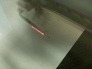
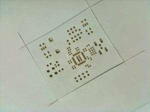
From the paste template file, I laser the mailing label with the Epilog 45W laser at work. My settings are "speed 25" and "power 25". I use raster mode, as it tends to produce more accurate, even results.
Then, I cut out the template. I leave enough border so I have some room to spread the solder paste without getting it on the board. I also need a border to hold on to when I peel off the label.
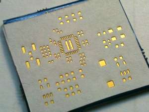
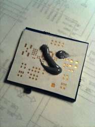
I clean the circuit board with rubbing alcohol to make sure there's no dirt or grime that will foul up soldering. Then I stick the template to the circuit board. Lining up the stencil is a bit tricky, but the mailing labels are only mildly sticky, and can easily be pulled up and reapplied if the alignment is off.
I've noticed that the mailing label adhesive gets stickier after being on the board a while. If you leave the label on the board for more than a day or two, it's very hard to remove without ripping (and messing up your solder paste).
Like Buttering Toast
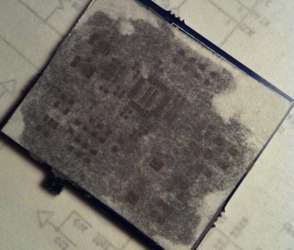
I apply the solder paste with a little metal squeegee. At first, I apply a lot of solder paste (several times what I need) and squeeze it against the board to get the paste deep into the template's holes. The layer of paste is very thick.
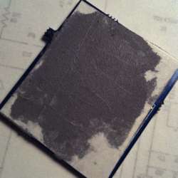
After I have a thick layer of paste on the board, I scrape off all the excess – until I can see the template paper through the paste. Sometimes, I wind up scraping some of the paste out of a hole in the template, so I have to re-apply the paste and re-squeegy it to be smooth.
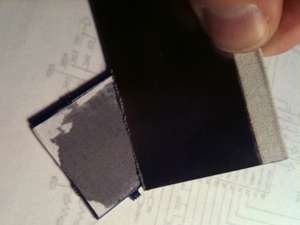
Once the solder paste is even, it's time to peel off the template!
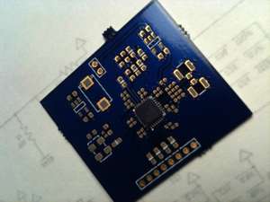
The hardest part of the whole process is placing the components on the board without damaging the solder paste. It's essential to have a good eyesight, a good pair of tweezers, a steady hand, and lots of patience.
If you do smudge your solder paste, you can try to reshape it with the tip of a pen knife. And if one of your components doesn't want to move into place, nudging it with the side of a pen knife blade seems to be the easiest way.
Turn On the Heat
After all the components are placed on the board, gently transfer it to the hot plate. Or better yet, put the board on the hotplate before you place the components.
Other people use fancy PID controllers to control their hot plate temperature. Since I'm building very small prototypes, I don't need a lot of temperature precision. I warm up the board to the point where I see the first wisp of smoke (130C or so, I think), then turn off the heat and let it sit for a minute to stabilize the temperature. I turn the heat back on until I see the solder melt on all the components. I immediately turn the heat off. I let the board cool down for a couple of minutes, then move the board off the hot plate to cool the rest of the way. I'm probably stressing the components by shock-cooling them…
Go Forth and Modify
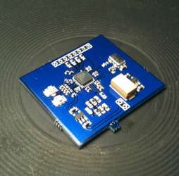
At this point, the board is done and it's time to hook it up and see it work! So far, all the boards I've made with this technique (four) have worked great (except for the solder flux incident). Good luck to all who try it, and I hope to see people discussing improvements…
Comments
Aaa, yes. Lasercutters are really cheap. NOT! Cool idea though if you happen to have one at work.
True enough, thus the "kinda" qualification. The good news is that they're becoming more affordable every day – kinda like laser printers did in the 80s and 90s. I hold out hope that laser cutters will be cheap enough for hackerspaces and groups (like my local BrainSilo or DorkbotPDX) could soon own one collectively, or that a generous citizen of the local community would offer their laser-ing services for stuff like this. It's also possible that people with laser cutters could offer an inexpensive commercial service that would involve cutting paper stencils and mailing them to people, hopefully for a fraction of the cost (per unit) of buying a Kapton or metal stencil. I think there's hope!
Wow! Didn't even know you could cut paper with a laser cutter without burning or scorching…now all I need is a few spare kilobucks! Can you cut thicker stock if you need deeper paste, it seems that the amount of paste would be quite minimal, and how well this works might have a lot to do with how much "tin" is left by the board house (which can vary quite a bit). As to manual placement of 0402s: you have a steadier hand than I do!
What about trying Post-It labels, the adhesive should be strong enough to hold to the board, and should be easier to remove. 3M has a large line of temporary adhesive products now, not bad for a failed adhesive, talk about lemons into lemonaid.
I think trying Post-It notes would be excellent. The only catch is buying ones that have adhesive on enough of the surface to cover the paste area. I haven't seen that kind of Post-It, but considering how many varieties they have in the store, there must be a product that'd cover this case! Next time I'm in an office store, I'll look for workable options.
How do you do double-sided pcbs? Is an oven the only way to do those?
I don't have a laser printer.. anyone recommend an online cheap laser printer service?
Have you tried this with Ball Grid Packages? It looks like the Xilinx is a PYP package?
Holla back! Jonesy
Jonesy, I've succeeded in soldering lots of 0402 resistors, capacitors, and inductors, and lots of fine-pitch QFN packages (with thermal ground pads). I haven't tried this with BGAs. I think it'll depend a lot on the pitch of the particular BGA you're using. I would like to try this technique (and reflow soldering in general) on a BGA package, but all the parts I'm interested in are really expensive – not something I want to experiment with…
A fair number of the lower-density Xilinx FPGAs (I'm thinking Spartan-3 and Spartan-6) come in PQFP, which is a lot easier to reflow solder. If you need a high-density part, BGA is the only way to do with with Xilinx. Perhaps another FPGA vendor (Actel, Altera, Atmel, Lattice) has parts with high density and a package that's easy to work with? I've also seen companies that sell FPGAs and CPLDs on breakout boards, which might help avoid the BGA issue.
If you do try to reflow solder your own BGAs, be sure to let us know how it worked and how you did it… I know that the pad and via layouts are tricky, and you may need to use a sophisticated PCB fabrication vendor to get the necessary via and trace sizes. A four- or six-layer board will be required to route all those signals away from the BGA.
Are these stencils a one shot detail or are they reusable?
Hi Russ. I think you might be able to reuse them, but I haven't tried. I'd bet the hardest part of reusing a paper label is not ripping it when removing it (hard to do if the label has been on the board for more than an hour or two), and cleaning the solder paste from the paper for reuse. It's probably not worth the trouble compared to getting a real metal or even Kapton stencil, if you're assembling dozens of boards. I view these paper label stencils more as a prototyping technique, where I want to build one or two boards and then test them out and make design changes.
I have ordered and used plastic mylar stencils ($35) from Pololo.
http://www.pololu.com/catalog/product/446
These have been reused, and worked well. I learned of Pololo from Sparkfun.
I do the same thing (make stencils with the laser). I use the transparencies made for laser printers. They are 3 mil thick which works out well for almost everything. The "trick" to using them with the laser is to to put a piece of glass under the plastic. This "sucks" the heat out of the plastic very fast and leaves a very nice edge. With the transparency you can see the board underneath; alignment is fast and easy. I use blue painters tape to hold them in place during the solderpaste application. This stuff doesn't leave any residue behind. I've done stencils as large as 6"x8" with pads for QFN-64's and 0402's without a single problem. Have fun!
Mike T: Good tip with the glass. I have friends who've tried plastic for templates but had problems with the edges melting. I'll let them know about this. I'm still pretty committed to mailing labels though – it's so nice to have something that's self-adhesive over the entire surface. (As discussed above,) I need to find some Post-It material and see if that's even better. It'd solve the one remaining problem I have with the labels, where the label doesn't come off cleanly from the board if I leave it on for too long (more than an hour or so).
Regarding reuse: I would suggest covering the paper with packing tape before cutting. Packing tape is my poor man's "lamination". I assume the laser cutter would still be able to cut it but I have no clue.
Great stuff- i will contact my lcoal laser cutters and see if they will rip me off or not
But i was thinking- if my local laser guys could cut me some steel sheet- Would it be a good idea to make a stencil that holds the IC's SMD's in the correct place by clamping the other stencil onto the pcb and just popping the SMD's/IC's in the correct place without applying force- pop into the oven for a while and let it do its thing. When it coold remove the placing stencil.. and viola? Ja of Not Ja?
@Peter: It's an interesting thought. I see a couple of challenges, though. First, you'd want to be sure not to damage the solder paste you'd applied. For many components, the solder paste extends past the edges of the components by a significant margin. So you'd need to enlarge the apertures for the components to not smash the solder paste. Secondly, it seems like you might wind up soldering the component template in place if the flux and solder takes too well to the template. It sure would be nice, though, if you could figure out a way to make it work…